This page has a selection of a few projects I’ve done over the years, some of the larger ones include an open source multimeter and FMCW radar, down to smaller ones like light up business cards and racing drones.
Hydra Meter - 2017-2023
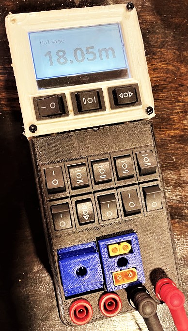
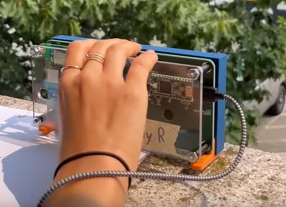
Ongoing project to build a multimeter. Currently (April 2024) at the stage of fully functional prototype, capable of doing regular voltage, current, and resistance measurements. I’m working on improvements to the onboard software and paired desktop application now, and plan to do a major iteration of the case relatively soon.
Image with acoustic data overlayed, showing the array locating a speaker
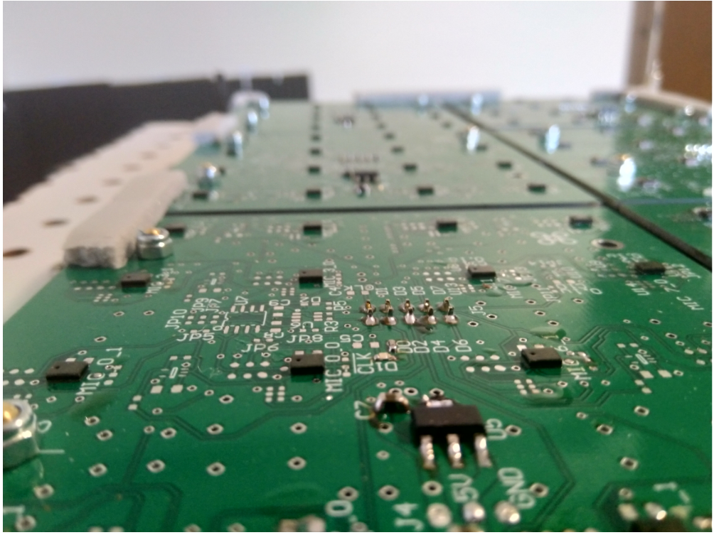
Deadbugged GbE PHY used for FPGA firmware debugging
LLRISE radar Internship project MIT Lincoln Lab - 2018
The LLRISE radar is a simple FMCW radar operating at 2.4GHz, which is used to teach students how radars work and give some hands-on experience. Part of my job at Lincoln lab was to redesign the radar to significantly reduce the BOM cost by making a separate RF board with SMD parts, instead of using connectorized ones from mini-circuits. I also redesigned the sweep generator and digitization, to use an ARM microcontroller with an internal ADC and DAC instead of analog signal generator and microphone input on a laptop. Between these and a few other changes to the design, the cost dropped from around $450 to $100, and significantly improved performance of the IF section.
Keeping the RF board, with its stricter requirements and more difficult SMD soldering, separate from the IF board, allowed a common RF section to be used on multiple versions of the IF section, of which I made two. One was optimized for size and cost, and to allow the whole system to be folded into a smaller space. This used SMD parts, and a more compact connector arrangement. The second board was optimized for simplicity and to be easy for students, most of who had never soldered before, to assemble by using large, through hole parts.
Another goal of the project was to simplify the physical construction. The previous design was very large and entirely 3D printed, which was expensive, slow to make, and occupied the lab printers for a long time for each. A The new design has only five printed parts, which use very little filament and can be printed very quickly with no support. The remaining parts are laser cut, which was chosen as it is significantly faster and cheaper for large components. The assembly can also be performed in less than five minutes with no tools, where the previous design would often take several hours.
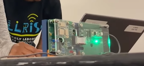
(To clarify, this video refers to the LLRISE program, in which high school students assemble and used the radar system for a few experiments. I did not participate in that program, I designed the systems they are using in it, this just shows them being assembled and used).
Picture of the finished system in use. The IF board is on the left, with the RF board on top of it (the part with all the shielded components, next to the top left screw), and the microcontroler board is on the right
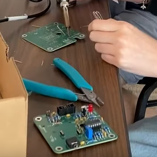
Assembled through hole IF board
NASA Robotic Mining Competition Iowa State University - 2016 & 2017
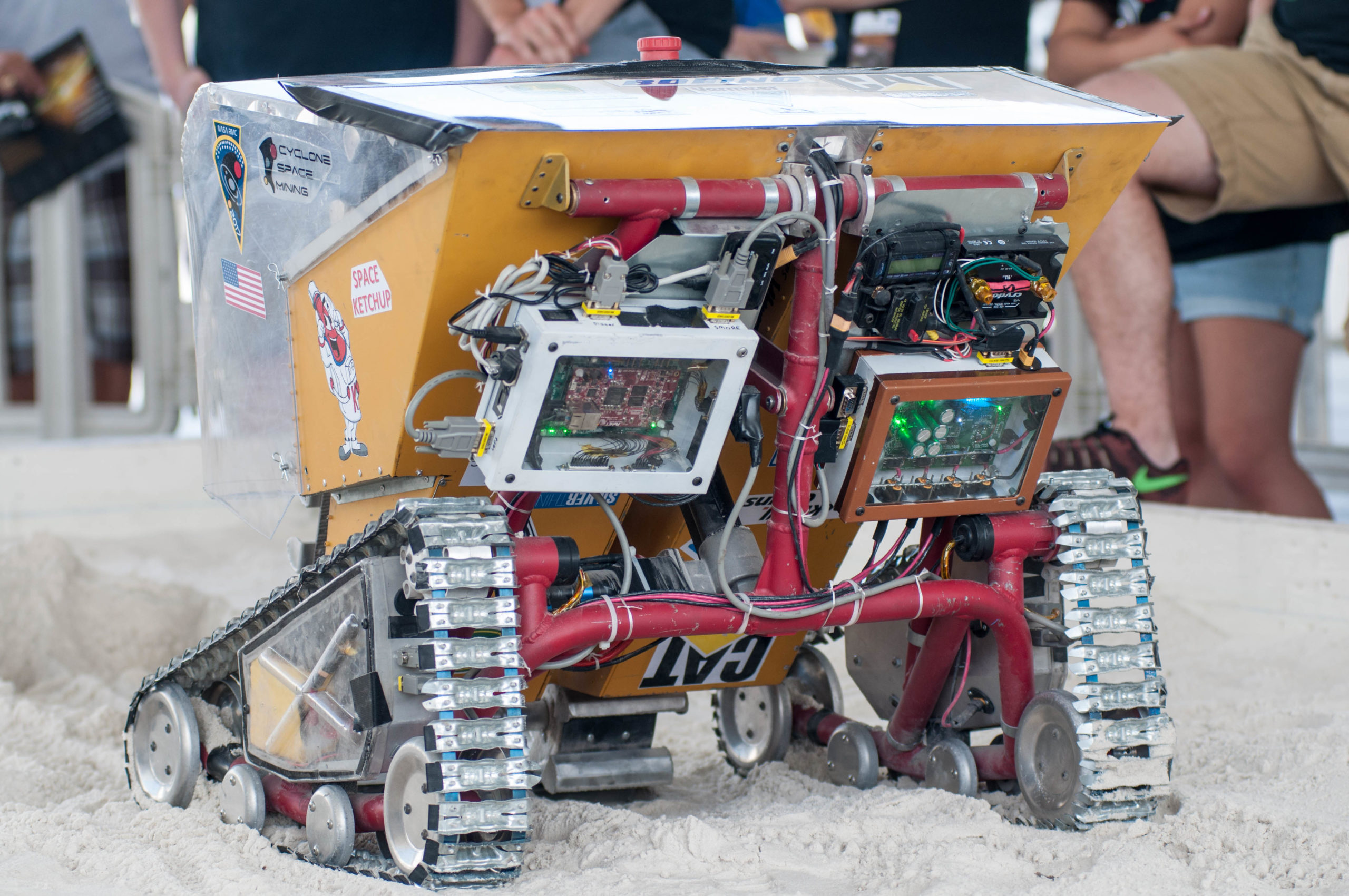
Designed, built, and tested control electronics for the twin robots entered in the 2016 and 2017 NASA RMC by Iowa State.
2017
Zynq 7020 based control system
White box on left side of the rear of the robot
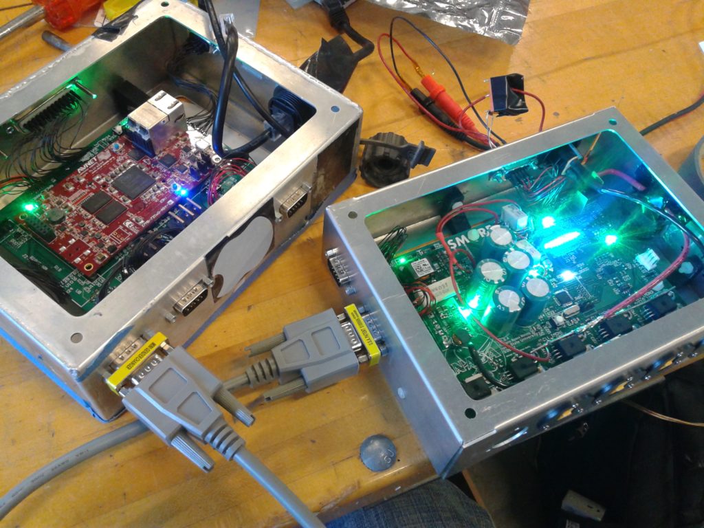
Power management system – Smart Management Of Robot Energy (S.M.O.R.E.)
Monitors and controls power for all motors, sensors, and the Zynq
Supercapacitor backup to allow graceful shutdown when power is cut
Black, brown and white box (sort of resembles a s’more) on the right side of the robot
2016
Control functions divided between Raspberry pi, Spartan 6 FPGA, and ARM microcontroller
Designed, ordered, assembled, programmed, and tested in less than one month
Rear view of 2017 robot, showing main controller, SMORE, and wiring
2017 electronics prototypes - Zynq board on left, SMORE on right
Colibri MIT Lincoln Laboratory - 2018
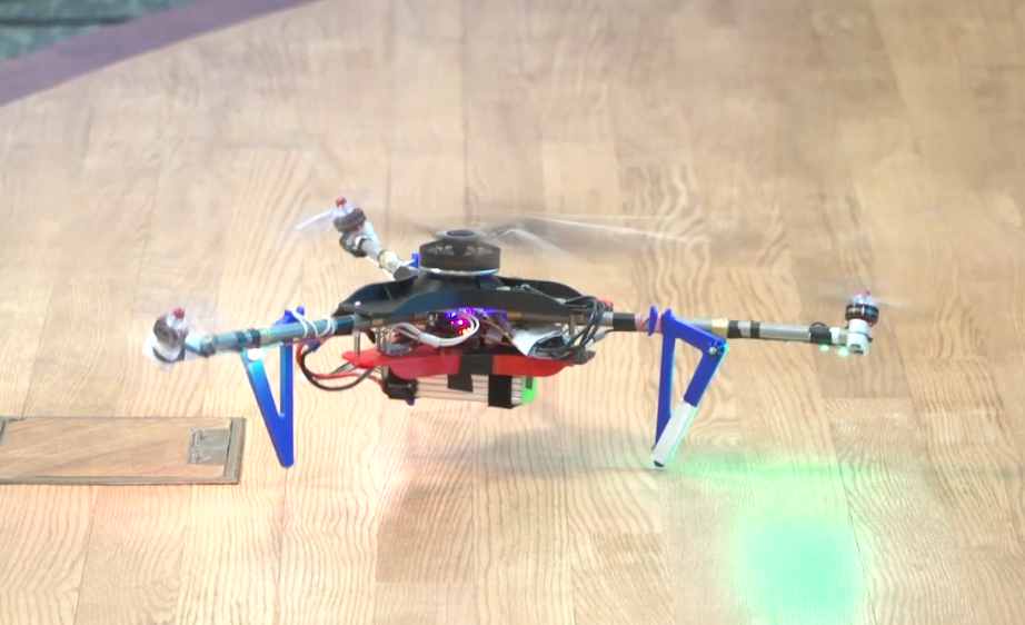
Colibri started as an Intern Innovative Idea Challenge (I3C) project between another intern, Peter Sharpe and I. It is a new type of multirotor that uses a single, large rotor for most of its lift, and three additional fixed rotors for control. The initial proof of concept was designed to demonstrate the layout and control system, and secure funding. The second prototype was built to demonstrate the feasibility of using a gas engine to directly power the main rotor.
Initial Proof-of-Concept
20″ main rotor
285 KV main motor
6S, 2200mAh battery
140W hover power
1.4Kg
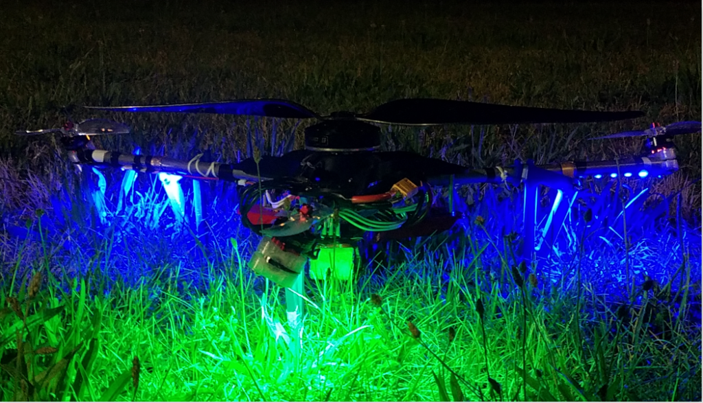
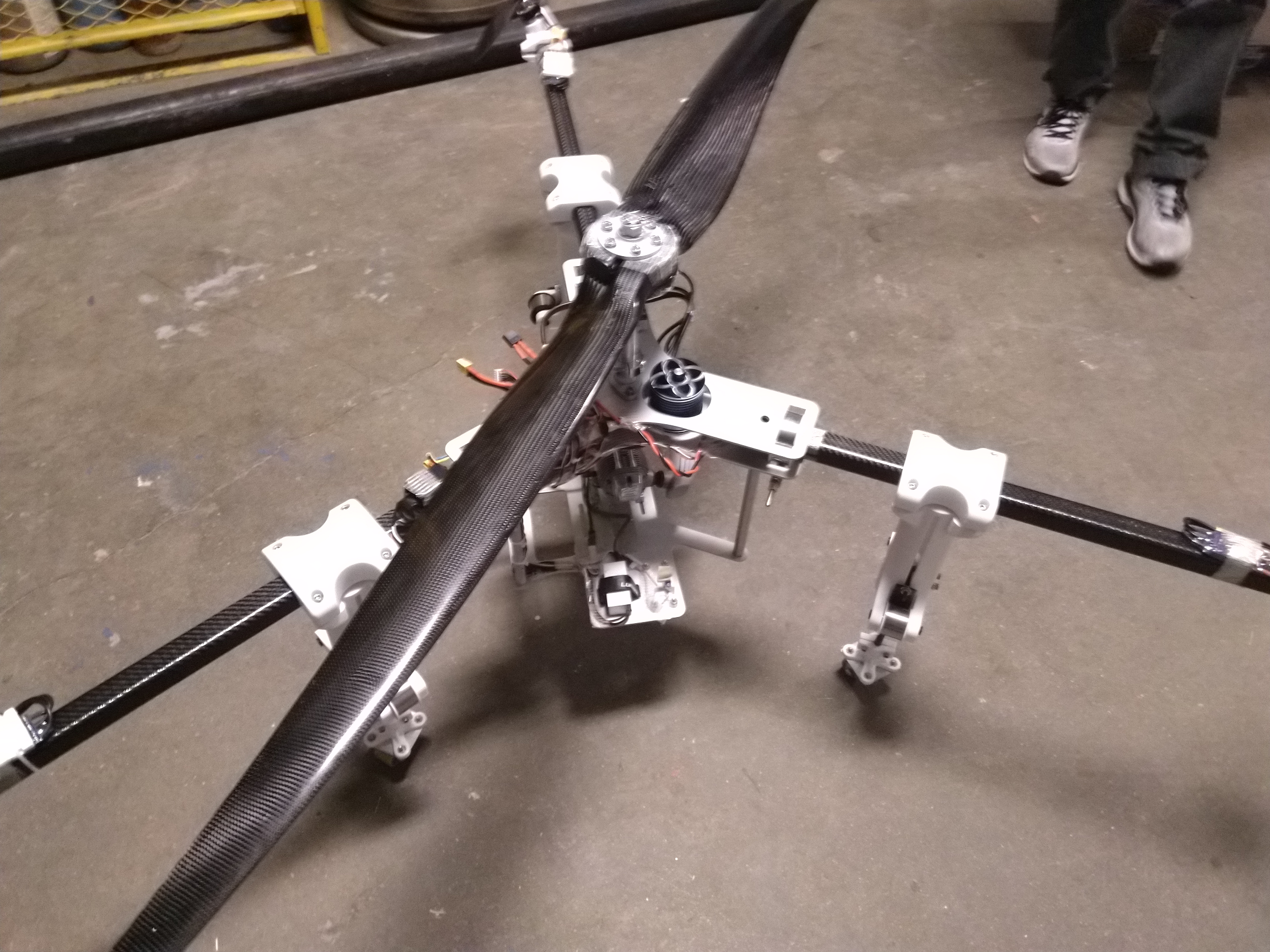
Second Prototype
48″ main rotor
1.2 HP 2 stroke engine
6S, 1000mAh battery
11Kg
The original prototype during final presentation to the lab management
Second-generation prototype with a gas powered main rotor
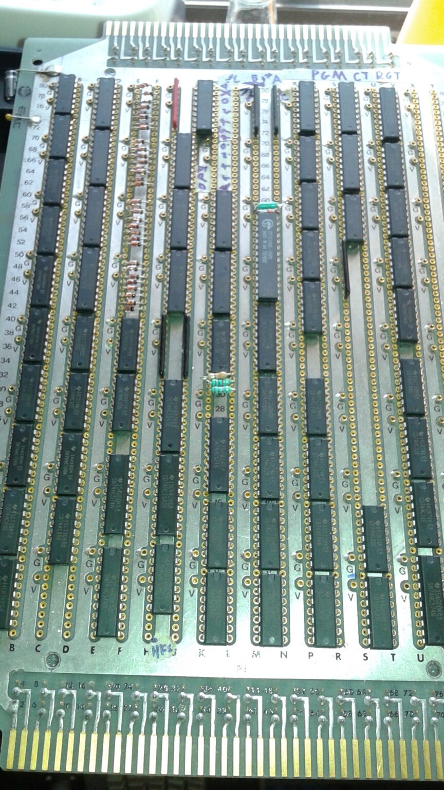
The MacroProcessor - 2014
This was a processor composed of discreet, 74-series logic chips and assembled on a wire wrap board. I designed and built this in High School as a way to learn about digital logic, processor design, and assembly programming. When starting, I had no experience with any of these, but was able to learn them together during the course of this project. The end result was not particularly useful or capable, since it’s purpose was entirely self-educational. In 2015, I ported the design to Verilog and got it running on an FPGA, as well.
Clock speeds reaching up to 100KHz
7 instructions
One program count register, two general purpose registers, two output registers
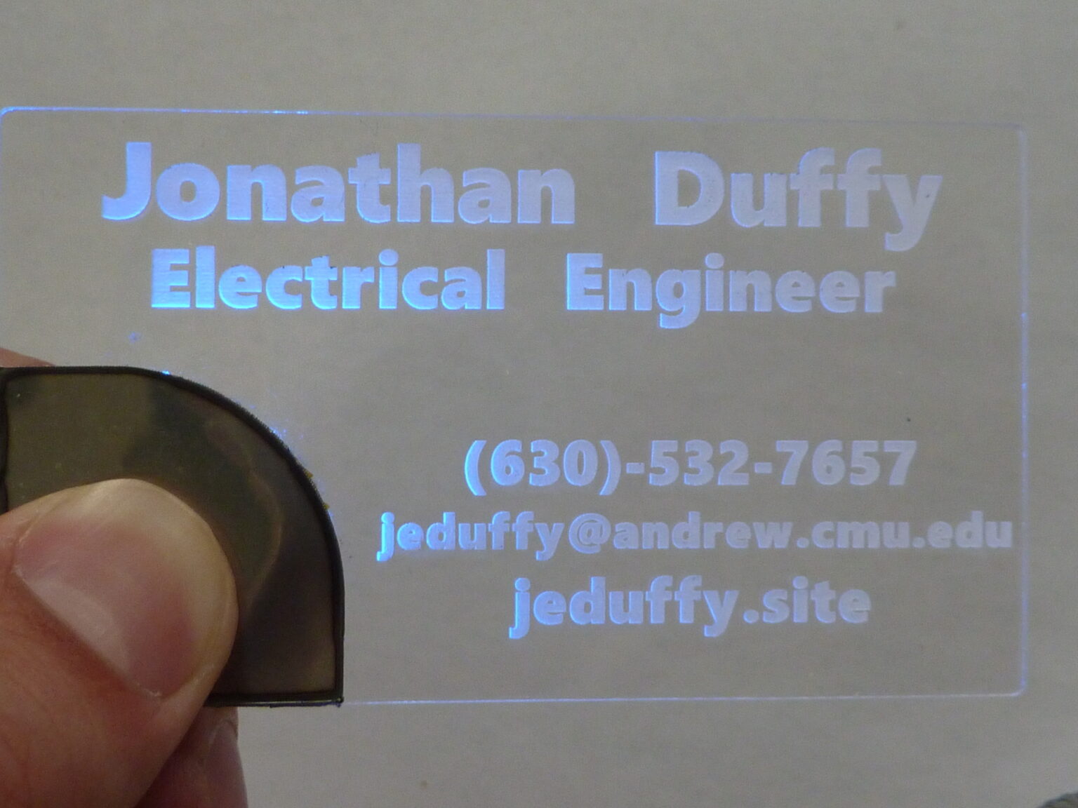
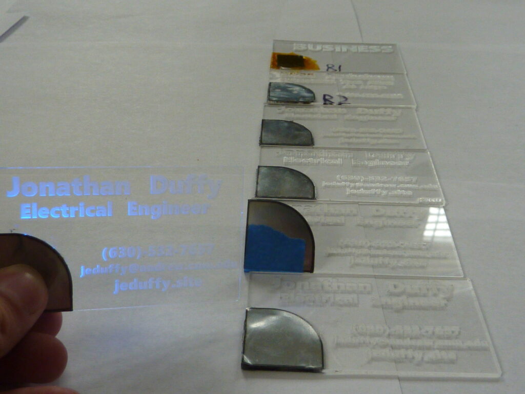
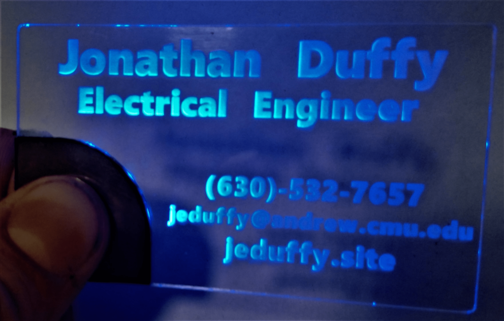
I designed and built these spring 2020 to make an impression when applying for jobs at my college career fair. They light up when held.
Revisions 1 (top) through 7 (bottom left), showing gradual progression to the final version, iteratively improving the appearance, reliability, and ease of manufacture. I made about 30 copies of the final version. Yes, the first one just says BUSINESS.
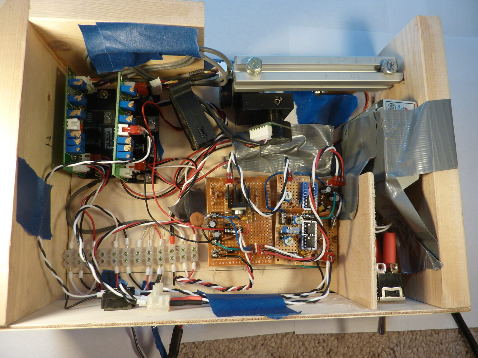
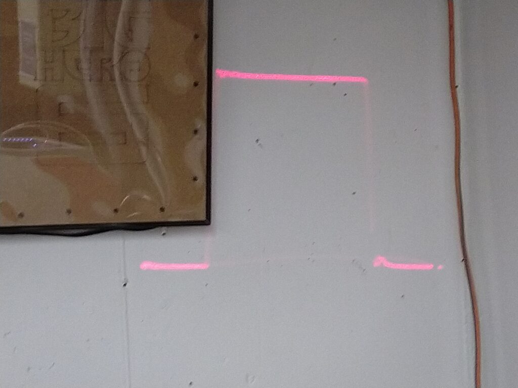
Laser galvonometer controller
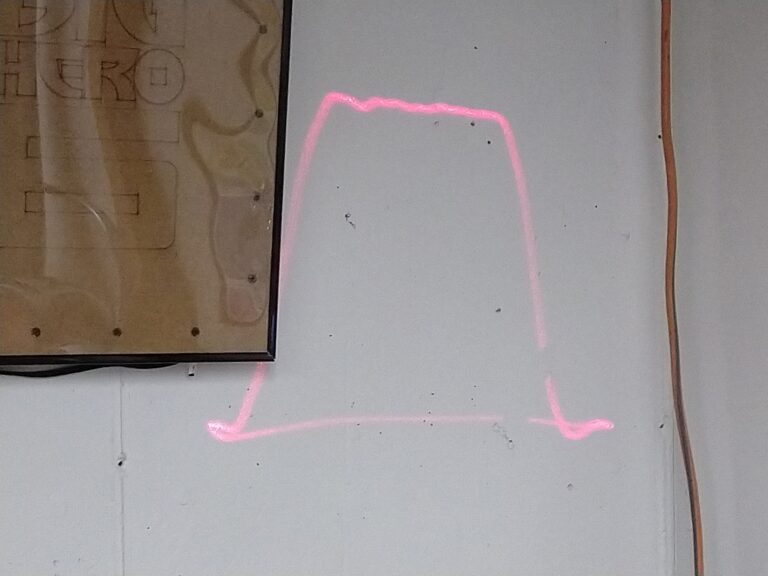
Designed and built in December 2019, this was an analog PD-loop feedback controller for a high-speed (20kpps) laser galvonometer.
Well-tuned step response
Poorly tuned step response
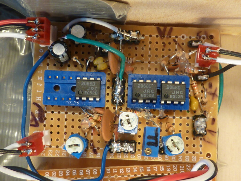
Close up of opamp feedback network
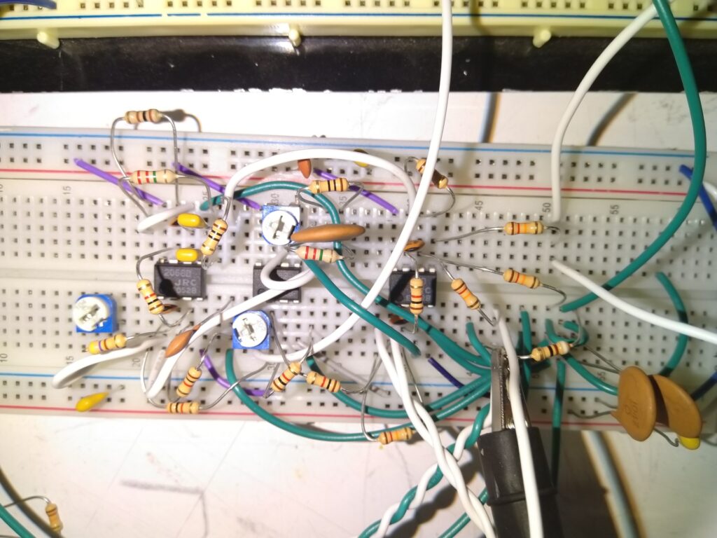
Feedback network on breadboard
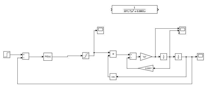
Simulink model of the system and controller
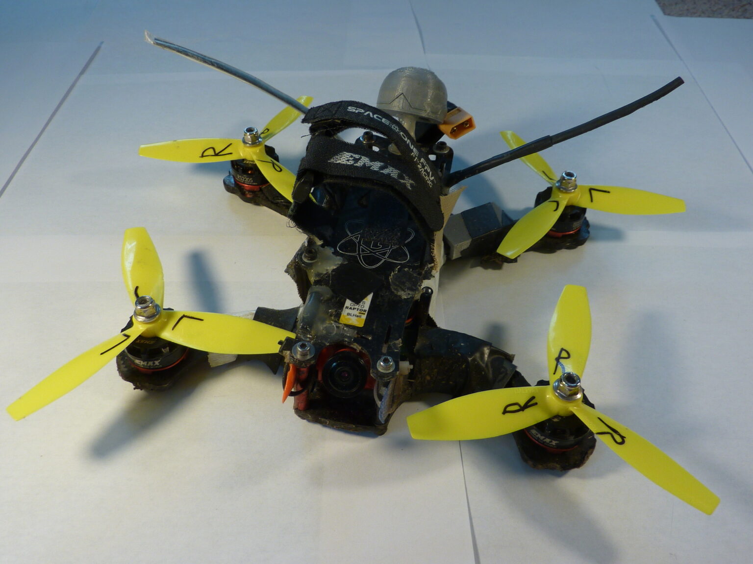
Racing Drones
I've been interested in drone racing since 2016, and have built a number of different racing drones over the years since. All feature radio receivers I designed and built, based around the RFM69HCW radio module.