Project - Multimeter
FebThis is an open source, highly modular multimeter project.
Current status (February 2026) is that version 1 has been completed, and a version 2 is nearly ready to order
I’ve put out a new video going over the entire design of version 1, and some of the changes coming in version 2:
Check out the video showing version 1 here:
https://www.youtube.com/watch?v=JMexSal01gQ
Version 2 ditches some of the modularity in favor of simplicity and cost – I’m starting with a slightly simpler version that I can produce a decent number of before doing back to having everything and the kitchen sink in one design again. This should also make it more accessible – lower entry cost and easier transition from normal meters. Check back soon to see the released V2 design!
Design philosophy:
(also why the name “Hydra”, and what do I mean by “highly modular”?)
Big design philosophy is on keeping it modular, the display and front-end are completely separate, as well as some of the internals for each. This is where the name Hydra came from, at some point down the road I’d like for a whole range of similar tools to all be able to connect and work together. I’m picturing something like a scope, with two regular channels, and a multimeter, function gen, and e-load all wired over to it and working together, like some multi-headed monster. It strikes me that often for an instrument like a multimeter, oscilloscope, function gen, etc. at least at the entry/hobby level, like a third of the cost is going to be in things like the screen, processor, power supply, chassis, etc. and it’s often difficult to find something that matches your needs. For example with a scope, I might commonly do something that requires 200MHz bandwidth, and another that requires 4 channels plus an external trigger, but I only need those to be like 5MHz. Normally you’d have to either have two separate scopes, or a 4-channel, 200MHz scope. What if instead I could buy a scope chassis with no ADCs/front ends, and separately get a single nice 200Mhz channel frontend, and three cheap 5Mhz ones? Might end up being a lot cheaper, and gives me room to grow if I find I want more channels, or more bandwidth, or whatever, without having to buy a whole new instrument. Or, what if I can even attach a multimeter frontend to my scope? It might not be super fast (couple Ksps), but far more precise, and synchronized with the high speed channels? That sounds really useful for all sorts of troubleshooting, can’t count how many times I’ve been trying to look at a scope screen and multimeter side by side on some misbehaving circuit and trying to judge when the meter reading changed relative to something on the scope. So, big design philosophy here is on having standardized, generic interfaces wherever possible, so that parts can be connected or swapped in and out.
Importantly, this modularity should be both internal and external. I often find that for big open source projects, it’s great that they’re open source, but people will often want some feature, and other people say “well, good thing it’s open source, just add it yourself! Duh!” without acknowledging just how big of a commitment it is to dig into some huge project like that to change something. If I just want the option to move some buttons around or something, I’m probably not going to spend months going through enough of the source code to understand how it all works, how to set up their environment, learn their conventions and styles, figure out how to change the thing I want, implement it, test it, and get it merged into the main branch. No, I’m probably just going to be really annoyed about it every time, or, use something else.
Counter to that here is to isolate complexity as much as possible – bring that barrier to entry down to something manageable in an afternoon rather than days or weeks or months. In pursuit of that, a few key elements will be made modular, for the meter front end, that’s the ADC, microcontroller, radio/communication interface, and it will have a generic “input module”. The input module has a fairly simple interface, all you need to do is match the pinout of some 0.1″ headers, physically fit in the slot, and put out an analog signal in the right range or digital signal over one of the three interfaces (SPI, UART, I2C). It’s intended to be the sort of thing you could throw together on perf board in an hour for some project-specific need. In addition to the meter itself, I’m starting off making two such modules for features I’ve always wanted in a meter, an XT-60 passthrough that can measure high currents (30+ A, and unfused so inrush doesn’t pop the fuse), and voltage simultaneously. I work on a lot of drones and robots, and use these connectors a *ton*, cant tell how many times I’ve tried holding two meter probes in the end of one with one hand concentrating *very* hard on not shorting them out while using the other to run a command or operate a remote. With this I can just plug straight into the meter, and, even measure things like power draw really easily.
The other main module I’m working on is an electronic load. There’s not a ton of space, so high sustained loads are out, but being able to do quick pulses or draw a couple dozen mA in a handheld meter would be super useful.
History of the project:
Background for this, in 2017, I was an intern at JPL and was running a test in a thermal chamber. Because things take time to heat up, it took several hours to run the measurement, and the chamber itself didn’t have any data logging capability. Which meant, I got to sit next to it in a basement and record numbers in a note book every couple minutes for about four hours straight.
A few days later I had to run the test again, and my supervisor mentioned that the multimeter I was using to measure temperature in the chamber could connect to a computer. In about an hour I’d written a little program to log the data from the device being tested and the meter into a spreadsheet, and just left it running on its own. This was pretty mind blowing to me, and I’ve wanted a logging meter ever since. At the time there weren’t any good cheap options, I looked at modifying my existing meter to output data but decided against it, and short story short, I figured “how hard would it be to just make my own?”
Turns out the answer is … “sort of very but also, not that bad”.
I went through a few revisions around then but ran out of time when I went back to school. I’d keep making little bits of progress over the following few years, but never actually had anything other than some drawings, simulations, and parts picked out. Until August 2023 when I decided this has sat on the shelf long enough, I’m getting this done already. Finally got a good enough design for the front-end, ordered parts, prototyped and debugged, and moved on to the first prototype. I had set myself a date in early November, the Hackaday Superconference, to get a prototype done by, and managed it! Not much came of that, but still a good incentive to just get this moving already. After getting that hacked together, I iterated on the software mostly for the next few months, and made a few updates, most notably to the case, ahead of Supercon 2024. After that, I considered version 1 complete and started moving on to version 2, for which I’m in the midst of testing a prototype board for a new frontend design, and doing some actual testing on the input protection.
Design - Revision 1.0
Video going through both the revision 1.0 design, and some new aspects of version 2:
Here is a written run-through of the version 1.0 design:
https://hackaday.io/project/176607-hydrameter/log/223270-schematic-and-operation
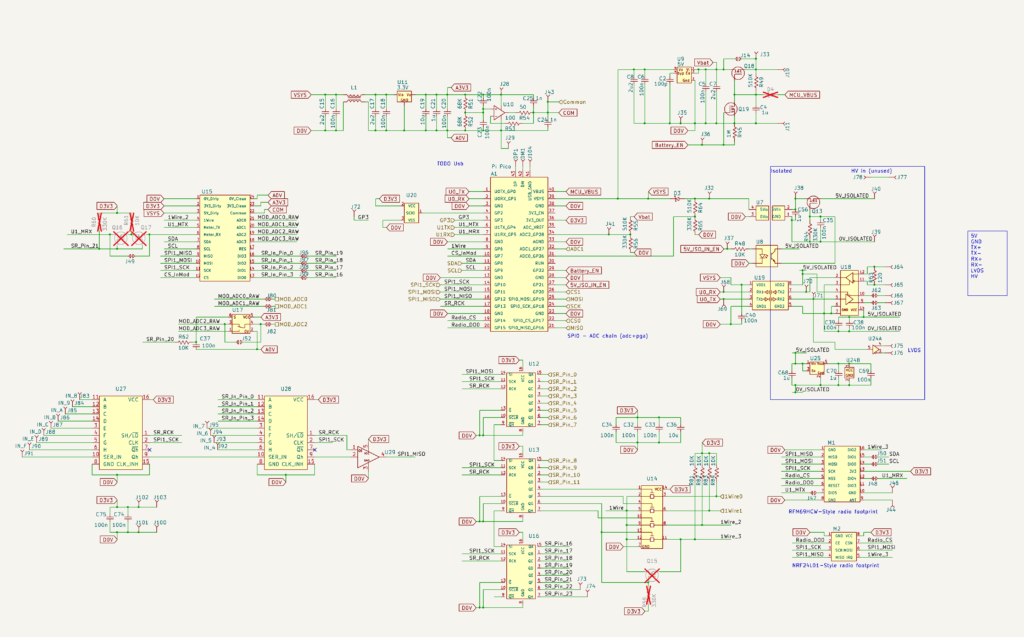
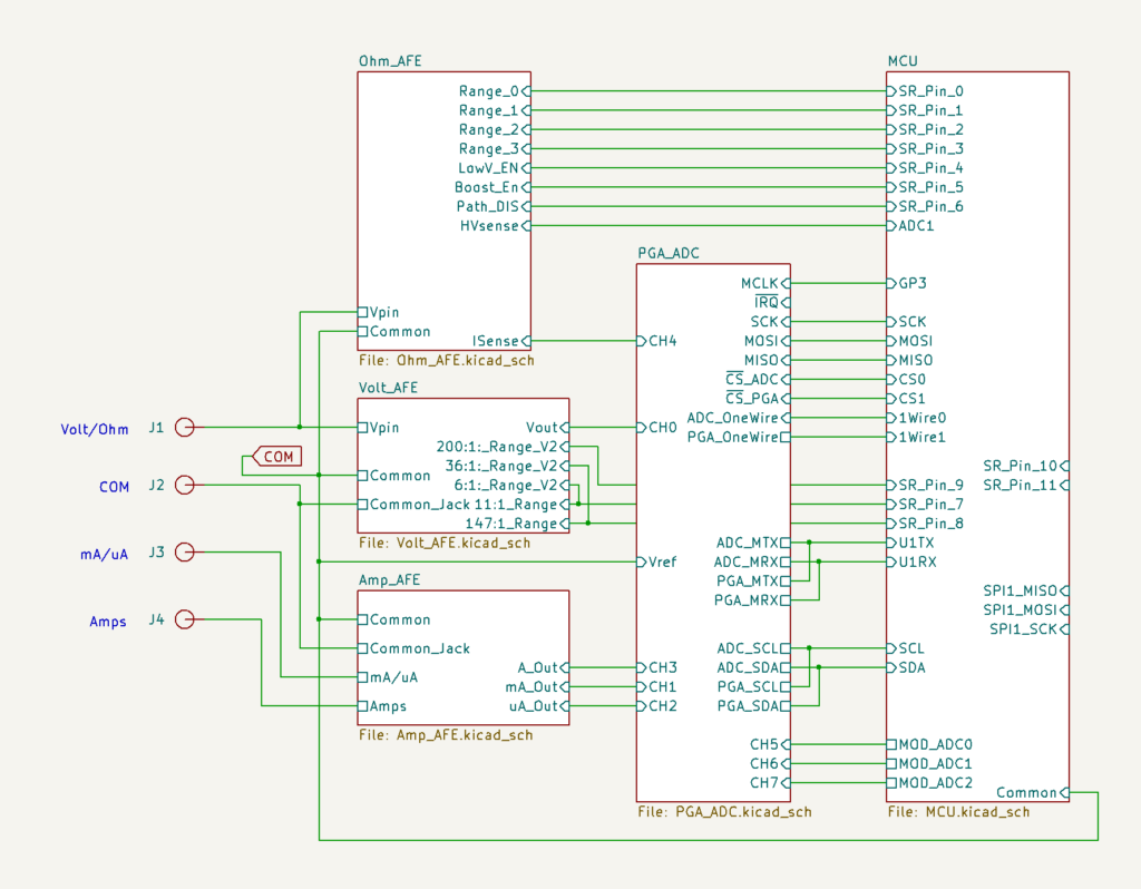
Top-level, only real points of note are that the front jacks go into three separate Analog Front Ends (AFE’s), Volts, Ohms, and Amps, analog outputs from those go to the PGA/ADC sheet, and the MCU has some IO that goes to each (except Amps).
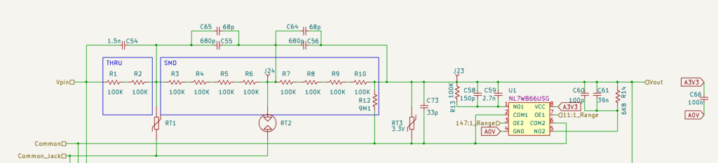
Voltage frontend
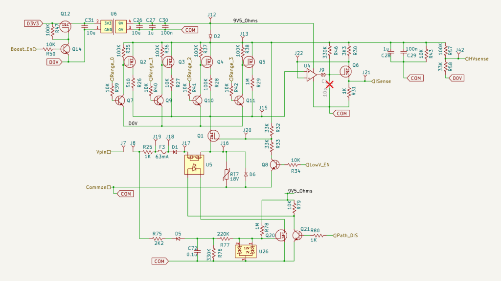
Ohms/resistance/diode/continuity fronend. This doesn’t measure resistance by itself, it just puts out a voltage at Vpin, and measures the current going out. The voltage across the DUT is then measured by the voltage frontend. We know current through it and voltage across it so V=IR and boom, resistance.
Current frontend. Switch between J5 and J6 to set mA vs uA.

Microcontroller and other assorted support stuff